

Custom Load Break Switch Design Strategies for Reliable Power Control
2026-09-18
Load break switches rarely get the attention they deserve until one fails to interrupt cleanly. Custom designs change that calculus—done right, they turn a generic switching point into a precisely matched component that handles your fault currents, ambient conditions, and duty cycles without drama. At Deepwill, we treat every custom load break switch as a small engineering project, not a catalog pick. In this post, we share the design strategies that separate reliable power control from expensive trial and error: arc extinguishing choices, contact material pairings, and mechanical interlocks that survive real-world abuse. If you've ever wondered why two switches with identical ratings behave so differently in the field, the answers start here.
Contact Materials That Keep Resistance Low After Years of Arcing
Low and stable contact resistance over the long haul isn't a matter of luck—it comes down to the metal you pick for the mating surfaces. Silver alloys with a small dose of graphite or nickel have proven themselves in switchgear that's been cycling for decades. The graphite acts like a microscopic lubricant, preventing micro-welds during arcing, while the nickel hardens the silver without sacrificing conductivity. You'll often see this combination in high-current disconnects that have to survive thousands of operations without a measurable rise in resistance.
Another quiet performer is silver tin oxide, especially in contactors that break inductive loads. The tin oxide forms a fine dispersion throughout the silver matrix, so when an arc blasts the surface, the oxide particles stay put and keep the contact from eroding into a pitted mess. Over years of arcing, these contacts maintain a relatively smooth interface, which means the actual metal-to-metal contact area doesn't shrink the way it does with pure silver. That's why you'll find silver tin oxide in elevator controls and industrial motor starters where downtime is expensive.
For the harshest conditions—think outdoor substation disconnects that face salt fog and frequent switching under load—silver tungsten or silver tungsten carbide can be the right call. Tungsten has an extremely high melting point, so the arc tends to bounce off rather than gouge the surface. The tradeoff is a slightly higher initial resistance, but after a few years the gap narrows because the contact face stays flat and clean. Maintenance crews often note that these contacts don't need the periodic sanding and re-torquing that other materials demand.
Arc Quenching Geometry for Compact Switch Enclosures
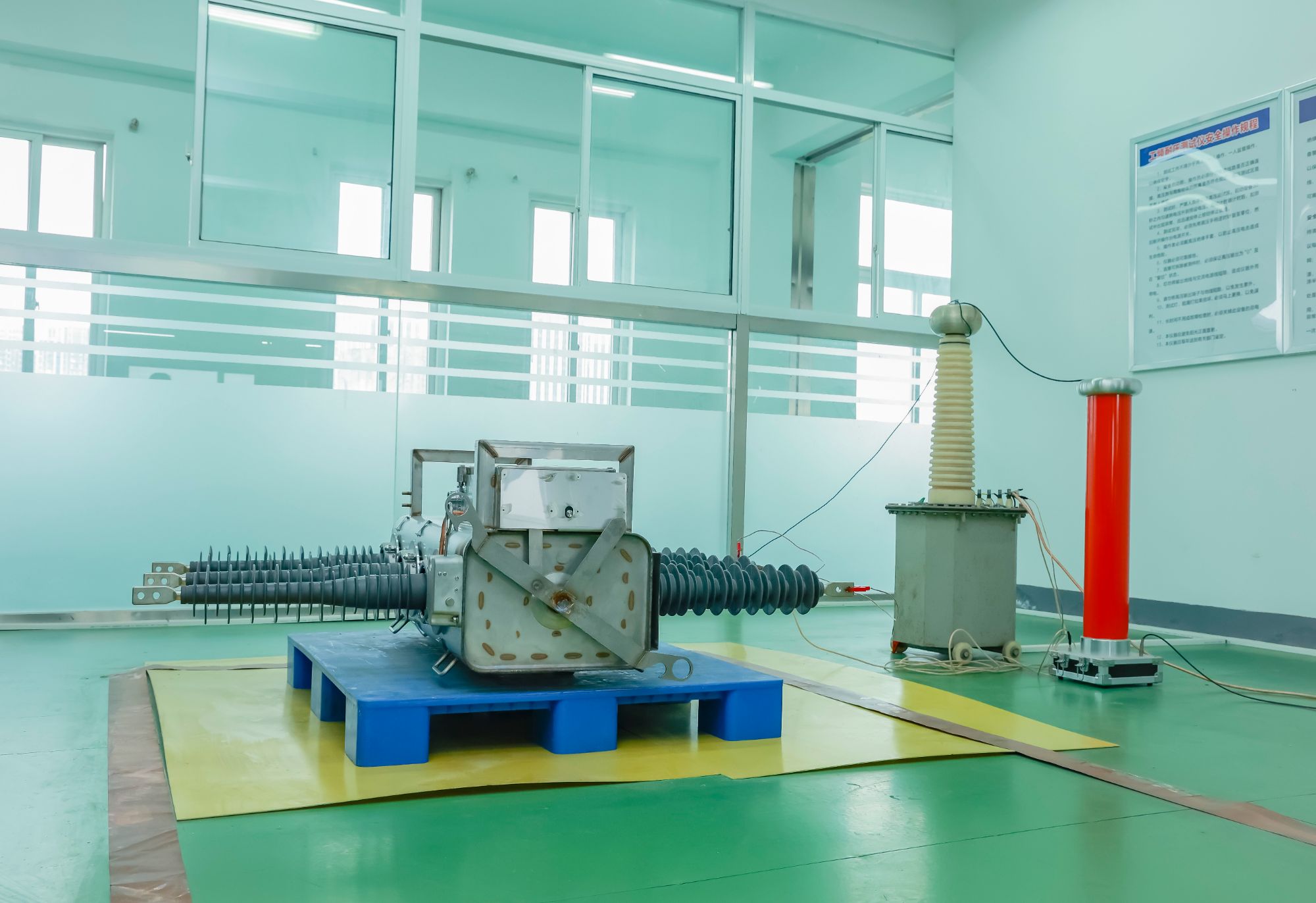
In compact switch enclosures, the geometry of the arc quenching chamber directly determines how quickly a fault current can be interrupted. Unlike larger cabinets with ample volume for gas expansion and cooling, tight spaces force designers to rely on splitter plates, narrow slots, and carefully angled arc runners. These elements stretch the arc column, raise its voltage, and drive it into regions where it can be cooled below the ionization threshold.
A practical example is the use of a U-shaped or V-shaped arc chute combined with a magnetic blowout coil. The coil produces a field that pushes the arc toward a stack of steel plates. Each plate splits the arc into multiple series arcs, increasing the total arc voltage while simultaneously absorbing heat. The plate spacing and vent geometry must be tuned so that exhaust gases do not accumulate or cause flashover to grounded parts. In very small enclosures, even a few millimeters of misalignment can lead to restrikes or thermal damage.
Another consideration is the material and surface finish of the quenching plates. Bare copper is rarely used because it erodes quickly; instead, steel plates with a thin oxide layer or ceramic-coated surfaces are preferred. The geometry of the vent openings at the top or sides of the enclosure also matters: they must relieve pressure without letting ionized gases reach live terminals. Some designs use labyrinth-like paths that force the exhaust to cool and deionize before exiting. This combination of arc stretching, plate segmentation, and controlled venting is what allows compact switch enclosures to interrupt high currents without occupying much space.
Managing Heat Rise Without Derating the Switch
Keeping a switch at its rated current doesn't have to mean accepting a hot-running enclosure. A more direct approach is to lower the thermal resistance between the junction or contact point and the surrounding air. This starts with the mounting surface: a flat, clean interface with a thin, even layer of thermal compound or a high-performance gap pad makes a surprisingly large difference. From there, adding a finned heat sink or a small fan can pull heat away quickly enough that internal temperatures stay within safe limits. In many designs, simply improving how heat leaves the switch is enough to avoid turning down the current.
There are also electrical adjustments that cut heat at the source. If the switch operates in a pulsed or switching mode, reducing transition time or adding a snubber network can lower the energy dissipated during each change of state. For mechanical contacts, checking terminal torque and using appropriately sized conductors prevents resistive heating at connections. Where practical, splitting the load across multiple poles or using a brief pre-charge circuit can shave peak currents. These steps help the switch carry its full rating without pushing its thermal envelope.
Designing the Operating Mechanism for Predictable Trip Forces
Predictable trip forces depend on how cleanly stored energy is released at the latch interface. A well-designed mechanism keeps the trip spring and latch contact in direct mechanical series, so the force needed to break the latch is dominated by only one or two well-known variables. When extra levers, links, or sliding surfaces enter the path, their individual frictions and dimensional errors stack up and make the trip point wander from unit to unit.
Separating the latching force from the main contact pressure gives a clearer threshold. The trip spring can be preloaded to a specific value and adjusted independently, while the main spring waits behind the latch. That way the operator or protection relay only has to overcome the modest, controlled force of the latch, not the much larger contact spring force. This reduces the sensitivity to slight differences in contact wear or contact spring tolerances.
Material selection and surface finish at the latch contact also play a large role. A polished, hardened surface paired with a roller or crowned follower promotes repeatable breakaway rather than stick-slip. Running a small series of force-displacement tests across the intended temperature range reveals whether the design stays inside the allowed trip-force band, and helps identify any pivot that needs a bushing or tighter clearance.
Voltage Withstand in Polluted and Humid Environments
Surface contamination rarely acts alone. When dust, salt, or industrial residues settle on insulating surfaces, they remain relatively benign until moisture arrives. High humidity, fog, or light rain dissolves soluble components of the pollution layer, turning it into a conductive film. The resulting leakage current follows irregular paths across the surface, heating localised spots and creating dry bands. These bands interrupt the current path, causing violent arcs that can bridge large portions of the insulator and trigger a flashover at voltages far below the rated withstand level.
Standard laboratory tests often use salt fog or a pre-applied solid layer with subsequent wetting to reproduce field conditions. However, real service introduces variables that are hard to simulate: uneven contamination build-up, alternating wet and dry periods, and chemical interactions between different pollutants. Engineers address these uncertainties through conservative creepage distance selection, using shed profiles that shield critical areas from direct washing, and by applying hydrophobic coatings. Silicone rubber has gained favour because it can transfer its water-repellent property to the pollution layer itself, suppressing conductive film formation even after prolonged exposure.
Field experience shows that maintenance schedules matter as much as the initial design. In coastal or industrial zones, periodic washing or replacement of heavily contaminated units remains essential. Some utilities now use online leakage current monitors to detect dangerous pre-flashover activity, allowing crews to intervene before a full outage occurs. The ultimate goal is not to prevent all surface wetting, but to ensure that any conductive path that forms remains too weak to initiate a destructive arc.
Endurance Testing That Mimics Real Utility Load Profiles
Constant-current or fixed-duty-cycle endurance runs rarely expose the weak spots that show up after years in the field. Real utility load profiles contain sharp morning and evening peaks, irregular motor starts, harmonic distortion from inverter-based equipment, and prolonged periods of light loading. Replaying these captured traces through a programmable AC/DC load bank forces the device under test to ride through the same thermal and electrical swings it will see on an actual feeder. The result is a much more honest picture of solder joint fatigue, capacitor aging, and connector wear than any steady-state test can provide.
A typical setup records one to four weeks of substation or smart-meter data at high resolution, then compresses the trace without losing the fast transients that matter. The test controller feeds this data to a regenerative electronic load while a thermal chamber cycles ambient temperature in parallel. Voltage sags, swells, and frequency drift are superimposed so the unit is stressed by multiple variables at once. What makes this approach work is that the sequence is repeatable, so design changes can be compared against the same load history rather than an abstract hour-count.
When endurance testing follows a real utility profile, failures tend to appear in the same order and location as field returns. Electrolytic capacitors near switching nodes fail earlier, optocouplers show CTR drift after repeated thermal cycles, and press-fit connectors develop higher contact resistance. Manufacturers can then fix these issues before the product ships. It also gives utilities a defensible way to qualify new hardware against their actual operating environment, because the pass/fail decision is tied to measured grid data instead of a generic test standard.
FAQ
A custom design starts from the specific duty cycle, voltage class, and environmental conditions of the installation rather than forcing those requirements into a pre-existing catalog product. The contact arrangement, actuation speed, and housing materials are then matched to the actual switching frequency, fault current exposure, and even the physical orientation of the panel. This approach eliminates unnecessary ratings while still meeting the most demanding interruption points.
Peak withstand current, recovery voltage, and the rate of rise of recovery voltage weigh heavily because they dictate how quickly the arc must be stretched and cooled. Higher inductive loads need longer contact travel and splitter plates shaped to drive the arc into cold deionized gaps. Continuous current rating affects contact mass and pressure, but it is the transient interruption behavior that really settles the geometry.
For medium voltage, designers often move from simple air breaks to puffer-assisted or magnetic blowout chambers depending on the interrupting medium. In air-insulated custom units, a puffer mechanism compresses air during the opening stroke and forces it across the arc, while in vacuum or SF6 alternatives the sealed interrupters become the primary arc control element. The choice often comes down to whether the switch must handle repetitive load breaking or only occasional isolation duties.
Sealing keeps moisture, dust, and corrosive vapors away from sliding contacts and insulating surfaces where tracking can begin. Without a proper IP-rated enclosure and shaft seals, humidity alone can create conductive films that reduce creepage distances and invite partial discharge. Custom designs often specify dual-layer gasketing and drain plugs with one-way valves to handle condensation cycles in outdoor or wash-down environments.
Mechanical endurance pushes the operating mechanism, latches, and contact wear through thousands of no-load operations, exposing fatigue and misalignment that a single high-current test might miss. Short-circuit testing proves the switch can survive an extreme event, but most real failures in custom load break switches come from slow degradation of springs, bearings, or arc chutes over everyday switching. Endurance testing under simulated site vibration and temperature swings gives a much better picture of long-term reliability.
Compactness requires careful use of insulating barriers, ribs, and slotted partitions rather than simply increasing spacing. Designers can shape the arc chamber so the arc path is guided away from grounded metal while keeping the live parts closer than a flat open design would allow. Using high-tracking-resistance molding compounds also permits smaller clearances, but every reduction should be verified through impulse and power-frequency withstand tests.
Scheduled visual inspections of contact erosion, arc chute carbon deposits, and hinge lubrication catch problems before they cause a misoperation. Infrared thermography under load can reveal hot spots from loose bolted joints or oxidized contact surfaces. Many operators also adopt a condition-based approach by recording operation counts and using torque checks on terminal connections rather than relying on fixed calendar intervals.
Sensors for temperature, partial discharge, and operation timing can be embedded in the housing or mounted on the operating shaft, but they must be isolated from the primary circuit through fiber optic links or galvanic barriers. The monitoring electronics are placed in a separate low-voltage compartment so that a sensor failure cannot create a conductive path across the insulation. This allows remote diagnostics of contact wear and mechanism speed while keeping the high-voltage isolation fully intact.
Conclusion
A load break switch that still opens and closes cleanly after years of service depends heavily on contact materials that resist welding and keep resistance low even when arc erosion has taken its toll. Pairing those contacts with a compact arc quenching geometry means the hot ionized gases are pulled away from the insulation and cooled before they can restrike, which is what allows smaller enclosures without sacrificing interrupting capacity. Heat rise is managed by designing current paths and terminal connections as a thermal network, adding ventilation or heat sinking only where temperature actually concentrates, so the switch holds its full rating instead of being silently derated.
The operating mechanism is tuned so trip forces stay predictable across the full travel, which prevents both nuisance trips and slow contact separation that prolongs arcing. For installations exposed to coastal salt, dust, or high humidity, creepage distances and shed profiles are sized to maintain voltage withstand even when surfaces are wet or contaminated. Endurance testing then validates all of these choices against load profiles taken from real utility operations—motor inrush, transformer inrush, capacitor switching, and low-power-factor interruptions—not just resistive lab cycles. This combination of material selection, thermal and mechanical design, environmental hardening, and realistic test sequences is what separates a custom load break switch that lasts from one that merely passes a catalog spec.
Contact Us
Contact Person: Julion
Email: [email protected]
Tel/WhatsApp: 8617351370631
Website: https://www.deyunelectric.com