

EMC Filter Manufacturer Guide to Choosing the Right EMI Filter
2026-10-18
Selecting the right EMI filter can feel like navigating a maze of specifications and standards—especially when system performance and compliance hang in the balance. As a seasoned DOREXS engineer once told me, 'the best filter is the one you never have to think about again.' This guide cuts through the noise, offering practical, manufacturer-level insights to help you choose with confidence. Whether you're battling conducted emissions or planning for future regulatory shifts, the following sections break down what actually matters—and what's just marketing fluff.
Start with the exact noise profile your EMI filter needs to suppress
Every EMI filter starts with a lie if you skip this step. You can't suppress what you haven't measured, and guessing at the noise signature usually ends with an overbuilt filter that costs too much or an underbuilt one that fails compliance testing on the first pass. Instead, capture the real conducted emissions from your device under worst-case operating conditions. Look at the spectrum from 9 kHz up to 30 MHz (or higher if your product demands it), and separate what's differential mode from what's common mode. The line impedance, the ground path, the switching frequency of your power supply—all of these shape the exact noise profile, and none of them should be assumed.
A useful trick is to run the device with a temporary line impedance stabilization network, or LISN, and log the emissions at multiple load points. You'll quickly see that the noise isn't a single hump but a series of peaks tied to switching harmonics, ringing, and parasitic resonances. Write down the dominant frequencies, their amplitudes, and whether they sit on both lines equally or mostly on one side. That asymmetry is your biggest clue: balanced noise tends to be differential mode, while noise that appears on both lines in phase is usually common mode. If you don't map this out, you'll end up choosing filter topologies by feel, and feel doesn't pass EMC labs.
One more thing worth doing before you touch a single component: probe the noise with and without your intended grounding scheme, because the filter's reference point changes everything. What looks like a simple 10 dB over-limit peak at 2 MHz might shift to 18 dB over when you move the chassis ground by a few centimeters. Write the exact profile into your design notes—frequency, amplitude, mode, and load condition. That becomes your filter's specification, not a generic list of "suppress high-frequency noise." From there, every inductor and capacitor choice has a target, and you stop wasting time on parts that fight the wrong frequency.
Match the filter's rated current and voltage to real operating conditions, not just the datasheet
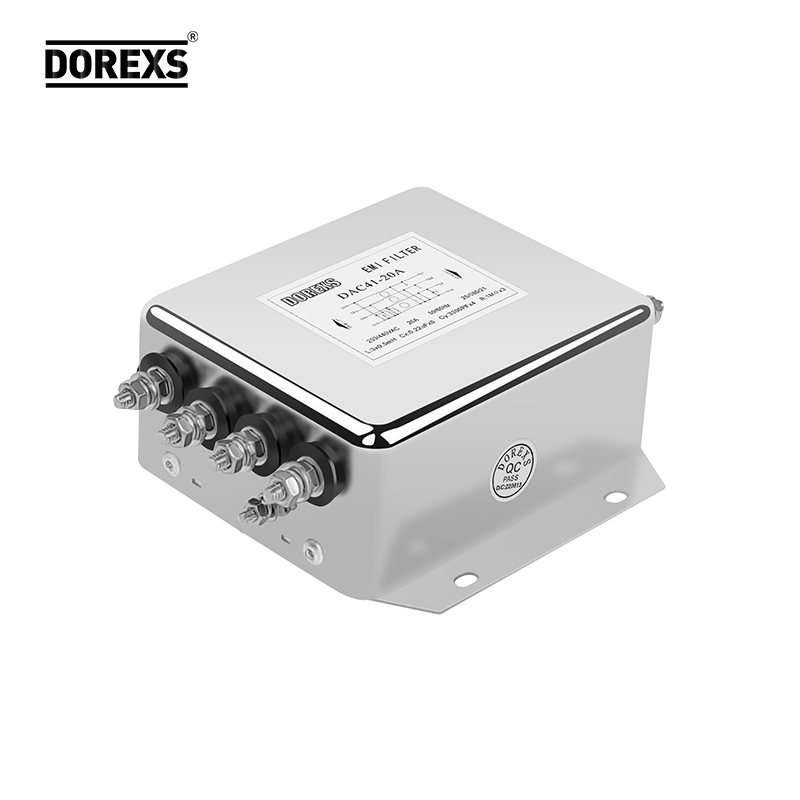
Datasheet numbers are a starting point, not a finish line. A filter rated for 10 A at 250 VAC might look fine on paper, but if your equipment sits near a motor drive or an old transformer, the actual line voltage could swing 15% above nominal, and harmonic currents could push the RMS current well past that 10 A mark. Pulling the datasheet and calling it a day is how you end up with overheated inductors and cracked capacitors six months into deployment. Instead, grab a power analyzer and log what the filter actually sees during startup, steady state, and any fault conditions you can safely simulate.
Pay attention to the ugly stuff: inrush current on cold mornings, voltage spikes from nearby switching, and ambient temperature inside the enclosure. A filter rated at 40°C ambient will degrade much faster if your panel sits in direct sunlight or next to a heat source. Likewise, if your load is non-linear—think variable frequency drives or LED arrays—the current waveform will have high crest factors, meaning the peak current may be double the average. Derating based on real measurements, not marketing specs, is the only way to keep the filter within its thermal and voltage stress limits.
One practical approach is to log the worst-case scenario for a full week, then add a 20–30% margin on both current and voltage before selecting a filter. Don't just look at the nominal rating; check the filter's surge capability and whether the capacitors can handle repeated transient overvoltages without losing capacitance. A filter that survives the datasheet test bench may fail in a dusty, humid, or high-vibration environment. By treating the datasheet as a hypothesis to be verified under your own operating conditions, you avoid costly field failures and warranty claims that no spec sheet will ever cover.
Read insertion loss curves as a practical map for the frequencies that matter in your application
Insertion loss curves are rarely just a single number buried in a datasheet; they are a visual fingerprint of how a component behaves across frequency. Instead of scanning the entire plot with equal attention, start by marking the specific frequency range your application actually uses. For a narrowband IoT radio, that may be a few megahertz around 868 MHz. For a wideband optical link, it could span dozens of nanometers. The curve's shape within that window tells you far more than any headline insertion loss figure ever will.
Look closely at the slope and ripple inside your band of interest. A flat, gently sloping trace means predictable performance and fewer unexpected reflections. Sharp dips or spikes, even if they appear outside your primary frequency, can indicate resonances that shift with temperature or manufacturing tolerance. If your signal has harmonics or sidebands that fall near those features, they can be attenuated or reflected in ways a single-point measurement would miss. Treat the curve as a topographical map: the valleys and ridges are the real terrain your signal must travel through.
Finally, compare curves from different units or batches, not just the typical plot from the vendor's website. Real-world insertion loss varies, and the width of that variation across your critical frequencies is often more important than the average loss. If the curve tightens into a narrow notch at your operating frequency, a tiny production shift could push you into deep attenuation. By reading the curve as a practical map rather than a certificate of performance, you can choose components that leave enough margin for the frequencies that truly matter.
Account for physical space, wiring length, and grounding before you settle on a package style
Package style decisions often get made on a whim—a familiar footprint, a tidy little datasheet drawing—but physical space rarely forgives that kind of haste. Before locking in a DIP, QFP, or a sleek BGA, measure the actual board real estate you can spare. Tuck a tall electrolytic next to a low-profile TSSOP and the enclosure lid might not close; press a wide SOIC into a corner meant for a slim SOT-23 and the solder joints start whispering complaints. Pull out the calipers, not just the schematic, and trace the keep-out zones around mounting holes, connectors, and heat sinks. A package that fits on paper can still collide with a standoff in the real world.
Wiring length is the quieter constraint, the one that shows up later as a ringing trace or a slow edge. The further a signal has to travel from die to pad to pin, the more inductance and resistance creep in. A tiny chip-scale part can shrink that path, but only if your layout lets the traces fan out cleanly. If you’re hand-soldering, those 0.4 mm pitch pads turn a simple repair into a squint-and-pray session. Think about how the package pulls your ground and power returns around the board: a sprawling DIP with a fat ground pin on the far corner might force a long, snaking return path that a compact QFN would have avoided. Short wires aren’t just tidy—they’re quieter.
Grounding is where package style stops being a preference and starts being a performance spec. A metal-backed package or an exposed pad gives you a direct thermal and electrical path to the ground plane, but only if you actually solder it down. Leave that pad floating and the chip runs hotter, noisier, and closer to the edge of its datasheet promises. Leaded packages with multiple ground pins spread the return current, reducing loop area, while a two-pin SOT-23 might force everything through one skinny bond wire. Before you settle, flip the board over in your mind: where will the ground vias sit? Can the package’s ground pins reach them without a daisy chain of stubs? If the answer is “sort of,” you haven’t accounted for grounding yet—you’ve just hoped it would work out.
Watch for impedance mismatches that can quietly undo a carefully chosen filter
When a filter is designed, it usually assumes a fixed source and load impedance—often 50 ohms in RF work. Drop that network into a real circuit where the driving stage has an output impedance that swings with temperature or bias, and the passband ripple can shift enough to eat away the stopband rejection you thought you had.
The problem gets worse with higher-order filters. A third-order Chebyshev might look perfect on the bench with a signal generator and a 50-ohm terminator, but connect it to a mixer or an ADC front-end with a reactive input, and the corner frequency can move, the group delay gets lumpy, and the return loss falls apart. You can’t fix that by tweaking component values alone unless you know the actual impedance spread.
One practical habit is to measure the source and load impedance across the frequency range before finalizing the filter. If they vary more than a few percent, consider adding a buffer, pad, or matching network with a known resistive termination. A pad wastes signal, but it often beats discovering that your carefully chosen filter only works in the simulator.
Verify safety certifications and long-term reliability claims against actual test data
A data sheet can list UL, CE, or IP ratings without showing how those marks were earned. Pull the corresponding test reports and compare the stated conditions to the environment your equipment will actually face. A certification issued for indoor use at 25°C means little if the unit will sit in an unventilated enclosure that regularly reaches 45°C. Look for the specific standard number, test duration, and pass/fail thresholds, not just the logo.
Long-term reliability claims often hide behind vague language like “designed for 10 years” or “MTBF over 100,000 hours.” Ask for the underlying accelerated life test data: sample size, failure count, confidence interval, and which failure modes were excluded. If the vendor cannot provide a test report with raw results, treat the claim as marketing rather than engineering.
Field returns and warranty repair rates are another form of actual test data. Compare the vendor’s predicted failure rate against what customers report after two or three years in service. A mismatch between lab projections and real-world returns usually points to an unmodeled stress, such as humidity, vibration, or voltage spikes.
FAQ
Look beyond the headline attenuation. The rated current and voltage are non-negotiable—pushing a filter past its rated current will saturate the inductors and kill its performance. Then check the leakage current, especially if you're working with medical or handheld equipment.
Not necessarily. At those frequencies, layout and grounding often contribute more than the filter itself. A filter can't fix a noisy return path. Try shortening the trace from the filter output to the load and make sure the chassis bond is low impedance.
A two-stage filter gives you more attenuation headroom, but it also adds bulk and cost. If your switching frequency is under 200 kHz and you only need to pass Class B by a few dB, a well-placed single-stage filter with good Y-cap placement might be enough. Start simple, then add a stage only if testing shows a specific band still over limit.
If the equipment touches patients or sits in a patient care area, leakage current limits drop dramatically—often to microamps. A medical-grade filter uses smaller Y capacitors and special insulation to stay within those limits. Don't assume an industrial filter will pass; the leakage spec is usually the giveaway.
It's tempting to standardize, but AC and DC filters are built differently. AC filters assume 50/60 Hz and are rated for line transients, while DC filters need to handle the ripple and inrush from rectified buses. Using an AC filter on a DC rail can cause overheating or resonance issues. Match the filter to the line type.
Insertion loss is measured in a 50-ohm system, which rarely matches your real impedance. Treat it as a relative comparison between filters, not an absolute guarantee. A filter with 60 dB insertion loss at 1 MHz might give you only 20 dB in-circuit if the source and load impedances are mismatched. Always verify with in-situ testing.
There's no universal filter, but you can find one that covers the worst-case limits if you verify the frequency ranges overlap. Military specs often add lower frequency conducted emission limits and higher surge withstand. A hybrid filter with combined X/Y stages and transient protection may work, but you'll likely need to test under both setups to confirm margin.
Filter components derate with heat. If your enclosure runs at 60°C, a filter rated at 25°C may lose 30-40% of its current capacity. Check the derating curve and pick a filter with at least 20% current headroom for hot environments. Also, ferrite cores can shift their attenuation with temperature, so re-test at operating temperature.
Conclusion
Choosing an EMI filter starts with capturing the exact conducted noise profile your device produces, not just a generic frequency range pulled from a compliance report. Look at the specific emissions peaks that appear during operation, then read the filter's insertion loss curves against those measured frequencies and your circuit's actual source and load impedances. A filter that shows excellent attenuation on a standard 50-ohm test bench can behave very differently when connected to a low-impedance switching supply or a high-impedance motor winding. Match the rated current and voltage to real operating conditions, including derating for elevated temperature, line surges, and continuous load, because the nominal datasheet numbers rarely reflect the worst-case electrical and thermal stress.
Physical layout and grounding deserve equal attention. Long input leads, shared return paths, and poorly bonded chassis connections can create parasitic coupling that bypasses the filter entirely, so settle on a package style only after mapping available space and verifying a short, low-inductance path to the ground reference. Finally, do not accept safety certifications or long-term reliability claims without asking for test data: temperature rise under full load, leakage current at maximum line voltage, and accelerated aging results for capacitors and potting materials. A practical filter selection is an iterative decision that combines measured noise signatures, impedance matching under actual operating conditions, mechanical constraints, and verified endurance data rather than a simple component swap.
Contact Us
Contact Person: Eric
Email: [email protected]
Tel/WhatsApp: 8618117837140
Website: https://www.emcdorexs.com