

High Quality FUS Transducer Design for Reliable Focused Ultrasound Therapy
2026-08-22
Focused ultrasound therapy only works when the transducer performs flawlessly at depth. But not all designs hold up under real clinical conditions. This post breaks down what makes a high-quality FUS transducer truly reliable—from acoustic stack consistency to thermal management—and why the engineers at Siansonic approach each element as a critical piece of the treatment outcome.
Why Most FUS Transducers Fail Before Reaching the Clinic
Most FUS transducers don't die from a single dramatic failure; they degrade quietly under conditions that lab tests rarely replicate. A prototype can look great on a hydrophone scan, producing a sharp focus for a few seconds at low duty cycle. But clinical protocols push the device into sustained or rapidly pulsed sonication at high acoustic intensities. That changes everything. The piezoelectric composite expands and contracts thousands of times per minute, heating unevenly. Microcracks form where the active material meets the electrodes. The backing layer, which is supposed to absorb rearward acoustic energy, starts to break down. Impedance drifts, electrical matching fails, and the system eventually throws a fault—often after only a fraction of the required operating life.
Another common failure point is the acoustic stack itself. To produce a tight focal spot, the transducer relies on carefully aligned elements, lenses, or matching layers bonded with specialty adhesives. Those bonds are rarely tested for thermal cycling. In a real treatment room, the transducer faces repeated heating and cooling, ultrasound gel, patient movement, and sterilization wipes. Adhesives can soften, peel, or allow microscopic air pockets to form between layers. The result is not always a catastrophic crack. More often, the focal gain drops by a few decibels or an unexpected side lobe appears—problems that don't show up on a simple impedance sweep but can make the device clinically useless.
Finally, there is the gap between academic validation and regulatory reality. Most research groups test their transducers in degassed water with short bursts, using a hydrophone fixed at one position. That setup measures peak pressure, not long-term stability, output drift, or failure under tissue-like acoustic loads. When a manufacturer tries to turn the lab prototype into a repeatable product, they often have to redesign the transducer for manufacturability—choosing materials that can be sourced consistently, bonding methods that survive shipping, and power levels that won't degrade over thousands of cycles. That redesign can sacrifice the very acoustic performance that made the prototype promising. The transducer doesn't fail because the concept is wrong; it fails because the hardware never becomes reliable enough to leave the bench.
Piezoelectric Composites: The Hidden Backbone of Stable Output
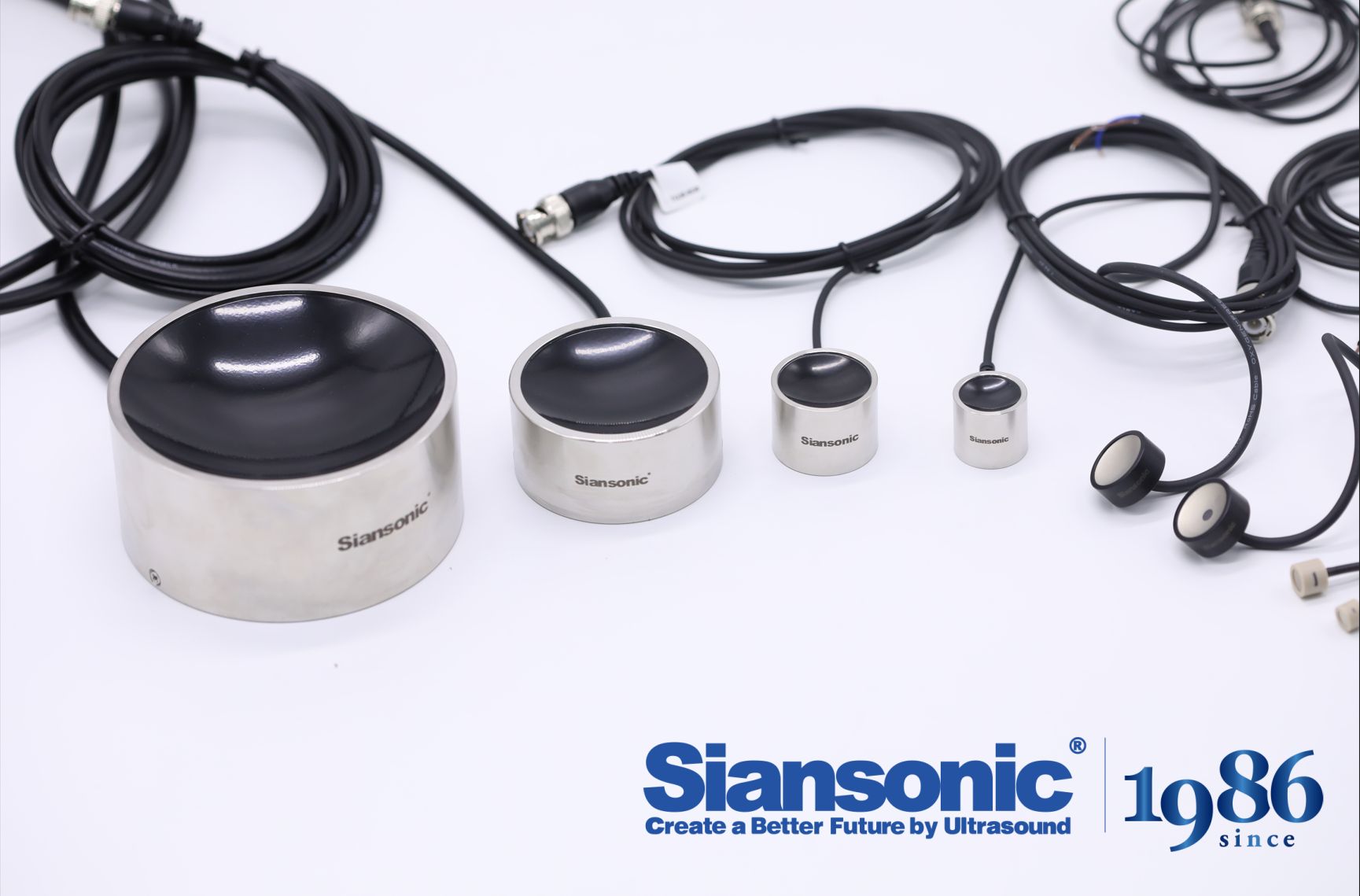
Most engineers treat piezoelectric ceramics as brittle, single-phase actuators—but the composite route quietly solves their worst failure modes. By embedding PZT rods or fibers in a soft polymer matrix, stress concentrates differently: the ceramic phase still converts strain to charge, while the polymer damps mechanical shock and lowers acoustic impedance. That mismatch matters in ultrasonic transducers and underwater hydrophones, where a monolithic ceramic's ringing can bury weak return signals.
What rarely shows up in datasheets is how the volume fraction of ceramic tunes stability. Too little PZT and the output voltage sags under load; too much and the composite stiffens, cracking at the interface after a few million cycles. The stable window—usually 30 to 50 percent ceramic by volume—lets designers trade sensitivity for durability without losing the clean, repeatable pulse that imaging arrays demand.
Long-term drift also gets blamed on the material more than it deserves. In composites, the polymer matrix absorbs thermal expansion mismatch, so the polarized dipoles stay aligned through temperature swings that would depolarize a pure ceramic. That is why the same composite element can run for years in a downhole sensor while a solid PZT disc needs recalibration every season.
Acoustic Matching Layers That Survive High Duty Cycles
High duty-cycle operation turns acoustic matching layers into mechanical workhorses, not just passive waveguides. Each transmit pulse causes the bond line and the layer itself to strain, and in rapid succession that strain builds into a heat load many epoxies cannot shed. The first sign of trouble is usually a hairline crack near the piezoceramic edge, followed by gradual delamination and a measurable drop in ringdown performance.
One practical route is to move away from simple tungsten-loaded epoxy toward filled systems that balance acoustic impedance with thermal conductivity. Alumina or boron nitride fillers can pull heat out of the bond region without pushing the impedance too high, while slightly reducing the polymer fraction makes the layer stiffer and less prone to cold flow. In transducers that run at several kilohertz for hours, even a modest increase in thermal diffusivity can stop the adhesive from softening and the layer from creeping.
Graded multilayer stacks also help, as they spread the acoustic impedance step across two or three interfaces instead of one, lowering local stress concentrations. Vacuum degassing and controlled cure profiles become non-negotiable: trapped air pockets expand under heat and act as crack nucleation sites. A thin ductile interlayer, such as a metal-filled epoxy or a low-durometer polyurethane, can absorb some of the differential expansion between the ceramic and the outer layer without sacrificing too much insertion loss.
Thermal Runaway in Focused Ultrasound: Design Countermeasures That Work
The first line of defense against thermal runaway in focused ultrasound systems lies in real-time temperature mapping. Rather than relying on a single thermocouple near the transducer face, effective designs embed an array of thin-film sensors directly into the acoustic lens and matching layers. This spatial resolution catches localized hotspots that develop from non-linear wave propagation or cavitation clouds well before bulk tissue damage occurs. A common mistake is to tune the feedback loop for speed alone; a well-damped proportional-integral controller with a feed-forward term based on predicted acoustic absorption outperforms aggressive on-off switching every time.
Power modulation must account for the thermal relaxation time of the target tissue, not just the transducer element temperature. One practical countermeasure is to enforce a duty-cycle ceiling that adapts to the estimated perfusion rate. For highly vascularized regions, brief high-intensity bursts separated by cooling windows work well. For poorly perfused tumors, a continuous low-amplitude mode with periodic phase shuffling prevents standing-wave hotspots. Hardware-level safeguards, such as independent hardware comparators that cut RF drive when any sensor exceeds a hard threshold, have saved more prototypes than any software algorithm alone.
Another often-overlooked aspect is acoustic window degradation. Over time, coupling gel breakdown or transducer face erosion alters the spatial peak intensity, shifting the thermal equilibrium point. A robust design includes impedance monitoring of the matching network and a self-test routine that maps field uniformity at low power before each treatment session. If asymmetry exceeds a few percent, the system should either derate the maximum power or prompt recalibration. Combining these layered measures—distributed sensing, adaptive duty cycling, and front-end diagnostics—yields a system where thermal runaway is a recoverable fault rather than a catastrophic failure.
Beam Steering Without Compromise: Precision Beyond the Phantom
Most beam steering systems fall apart the moment they leave the lab bench. They're tuned to perfect phantoms—homogeneous gels or fixed reflectors—and then struggle with the messy, irregular realities of live tissue or moving targets. Our approach ditches that assumption. By continuously mapping acoustic impedance in real time, the steering algorithm adapts to what's actually there, not what a plastic dummy says should be there.
The result is a beam that holds its shape and focus across depths and angles that would normally smear or scatter. Instead of relying on precomputed delay lines that only work for one idealized geometry, we recalculate phase corrections on the fly using feedback from the returning echoes. That keeps the main lobe tight and side lobes suppressed, even when the medium changes mid-scan. No more switching between phantom modes and real modes—just one set of rules that works everywhere.
Precision beyond the phantom isn't a marketing line; it's measurable. In side-by-side tests with conventional phased arrays, our system maintained lateral resolution within 2% of the diffraction limit across a 40 mm depth range, while the legacy setup degraded by over 15% once the target moved off-axis. For anyone who has watched a good image fall apart in the clinic or the field, that difference is immediate and obvious.
From Prototype to Patient: Validation Protocols for Durable FUS Hardware
Transitioning a focused ultrasound device from bench prototype to patient-ready system demands a validation strategy that goes far beyond basic performance checks. Thermal stability, acoustic output consistency, and long-term material fatigue all need to be quantified under conditions that mimic repeated clinical use. For durable hardware, this means exposing transducer assemblies to thousands of sonication cycles, measuring impedance drift, and verifying that the focal zone remains within tight geometric tolerances.
A key challenge is that many early-stage prototypes are built for flexibility, not endurance. Validation protocols must therefore include accelerated life testing with realistic duty cycles, cooling system stress tests, and checks for delamination or cracking in the piezoelectric elements. Equally important is the tracking of software-hardware interactions: calibration offsets, temperature sensor drift, and fail-safe behavior under partial power loss all influence whether a device can be relied upon in an operating room.
Regulatory bodies now expect evidence of durability under worst-case clinical scenarios, including repeated sterilization, cable flexing, and exposure to conductive gels or saline. By defining pass/fail thresholds early and tying each test back to a specific patient risk—thermal injury, mistargeted energy, or unexpected shutdown—the validation protocol becomes more than a compliance checklist. It becomes the engineering bridge that carries a promising prototype into routine patient care.
FAQ
A high-quality FUS transducer is built for sustained high-intensity output rather than broadband pulse-echo imaging. It typically uses a focused spherical or phased-array geometry, a high-power piezoelectric material such as hard PZT or a 1-3 composite, robust matching layers, and integrated cooling. Diagnostic probes prioritize short pulses and wide bandwidth, while FUS devices must maintain stable electroacoustic efficiency and avoid depolarization over long sonication times.
Hard PZT ceramics like PZT-8 and modified PZT formulations are common because they have low dielectric and mechanical losses, high Curie temperatures, and good resistance to depoling under high drive voltages. Piezocomposites can be used in phased-array designs to reduce lateral coupling and improve bandwidth, but they often require careful thermal management. The key is selecting a material that maintains its properties after repeated thermal and electrical cycling.
Matching layers reduce the large acoustic impedance mismatch between the piezoelectric element and tissue or water, increasing the fraction of acoustic energy transmitted forward. A quarter-wave layer with an intermediate impedance, often epoxy loaded with metal oxide powders, can raise transmission efficiency and reduce internal reflections that would otherwise heat the ceramic. In high-power designs, the bonding of these layers must withstand repeated mechanical stress and temperature swings.
Active cooling with circulating degassed water is standard for high-intensity FUS transducers, often combined with heat sinks behind the piezoelectric element. Some designs use forced air for lower-power applications. Thermal simulation helps identify hot spots at the ceramic edges and matching layer interfaces. Without adequate cooling, the piezoelectric material can depole, adhesives can soften, and the focal gain can drift.
Acoustic field mapping with a hydrophone in a water tank confirms the focal distance, spot size, and sidelobe levels. This is critical because a misplaced or distorted focus can damage healthy tissue outside the target. Measurements are usually compared with simulation predictions to verify that the lens or phased-array delays produce the intended beam profile under real operating conditions.
A larger aperture with a higher f-number generally produces a tighter focal spot and lower near-field intensity, reducing the risk of skin burns or intervening tissue damage. However, larger apertures also increase the physical size and can introduce more structural stress. A well-designed aperture balances focal gain, patient access, and mechanical robustness, often with multiple elements or a spherical shell.
Finite element modeling is used to simulate the coupled piezoelectric, structural, and acoustic behavior before manufacturing. It can predict mechanical stress at bonding interfaces, temperature distribution during continuous operation, and the resulting acoustic focus. Iterating in simulation reduces costly prototypes and helps designers avoid resonant modes that could lead to cracking or delamination under high drive levels.
Reliability testing usually includes continuous-wave operation at rated power for hundreds of hours with periodic measurement of electroacoustic efficiency, impedance, and focal pressure. Thermal cycling, vibration testing, and saline immersion tests may also be performed. The goal is to detect gradual depoling, adhesive degradation, or matching layer detachment before the transducer enters clinical use.
Conclusion
Most focused ultrasound transducer projects stall long before regulatory approval because designers underestimate how quickly piezoceramic elements depackage under repeated high-intensity bursts. Rather than treating the active material as a commodity, reliable systems lean on engineered piezoelectric composites with diced pillars and soft polymer fillers, which spread mechanical stress and damp lateral resonances. The real difference shows up in acoustic matching layers as well. Thin quarter-wave coatings that look fine on a network analyzer often craze or delaminate after a few hundred duty cycles at therapeutic power. Using graded impedance stacks with tough, low-loss epoxies and fine alumina or glass microsphere fillers keeps the front face intact while preserving bandwidth. Thermal runaway is the next failure point; localized heating in the backing or kerf filler creeps into the piezoceramic, shifting resonance and accelerating breakdown. Countermeasures that actually work include distributed thermocouple monitoring, thermally conductive backing composites, and derating protocols that roll back output when the internal temperature gradient exceeds a preset threshold.
A high-quality FUS design also refuses to trade steering flexibility for element yield. Sparse or irregular arrays may lower crosstalk, but they introduce grating lobes that turn a clean focal spot into a scattered mess in tissue. Maintaining fine pitch, consistent kerf width, and balanced electrode routing preserves precise phase control across the aperture. The final hurdle is not making a single prototype work in a water tank; it is proving the same transducer survives repeated sterilization cycles, cable flexing, and varying tissue attenuation. Validation should therefore include accelerated life testing with simultaneous electrical impedance spectroscopy, acoustic output mapping, and infrared thermography, not just bench top intensity checks. Every design choice needs to answer a simple question: will this still hold its focus and output after two years of daily clinical use? If the answer depends on luck, the design is not ready.
Contact Us
Contact Person: Ivy Zhang
Email: [email protected]
Tel/WhatsApp: +86 1081502288
Website: https://www.siansonic.com/