

Profile Projector Factory: Inside the Manufacturing of Precision Optical Comparators
2026-09-18
Walk through a JATEN profile projector factory and you'll quickly see that optical comparators aren't just bolted together—they're coaxed into existence through rigid castings, hand-finished optics, and calibration routines that chase away every last micron of error. This post takes you inside the manufacturing floor to reveal how raw materials become the precision inspection tools that quality labs rely on daily.
The Furnace Room Where Raw Glass Turns to Precision Lenses
Inside this room, the air carries a dry, constant heat that makes the skin tighten after a few minutes. Racks of raw glass blanks sit near the entrance, their surfaces cloudy and unremarkable. Workers move with a quiet economy, checking furnace temperatures that hover well above a thousand degrees. No two shifts feel identical, because the glass responds to humidity, barometric pressure, and the smallest impurities in the batch.
Once the blanks soften into a glowing, honey-like state, they are pressed or slumped against precision molds. This is not a single dramatic moment but a slow negotiation between heat, gravity, and tooling. Technicians adjust the dwell time by seconds, and those seconds decide whether a curve will focus light cleanly or scatter it. Every lens passes through multiple furnace cycles, each one refining the surface closer to its intended radius.
By the final cycle, the lens still looks fragile but no longer random. Its edges have become uniform, its curvature held to tolerances measured in microns. Inspectors use collimated light rather than casual glances, looking for striations or stress that could distort an image. Only after that check does a raw piece of glass earn the right to be called a precision lens, leaving the furnace room with a quiet proof of controlled fire.
Machining the Cast Iron Base That Anchors the Light Path
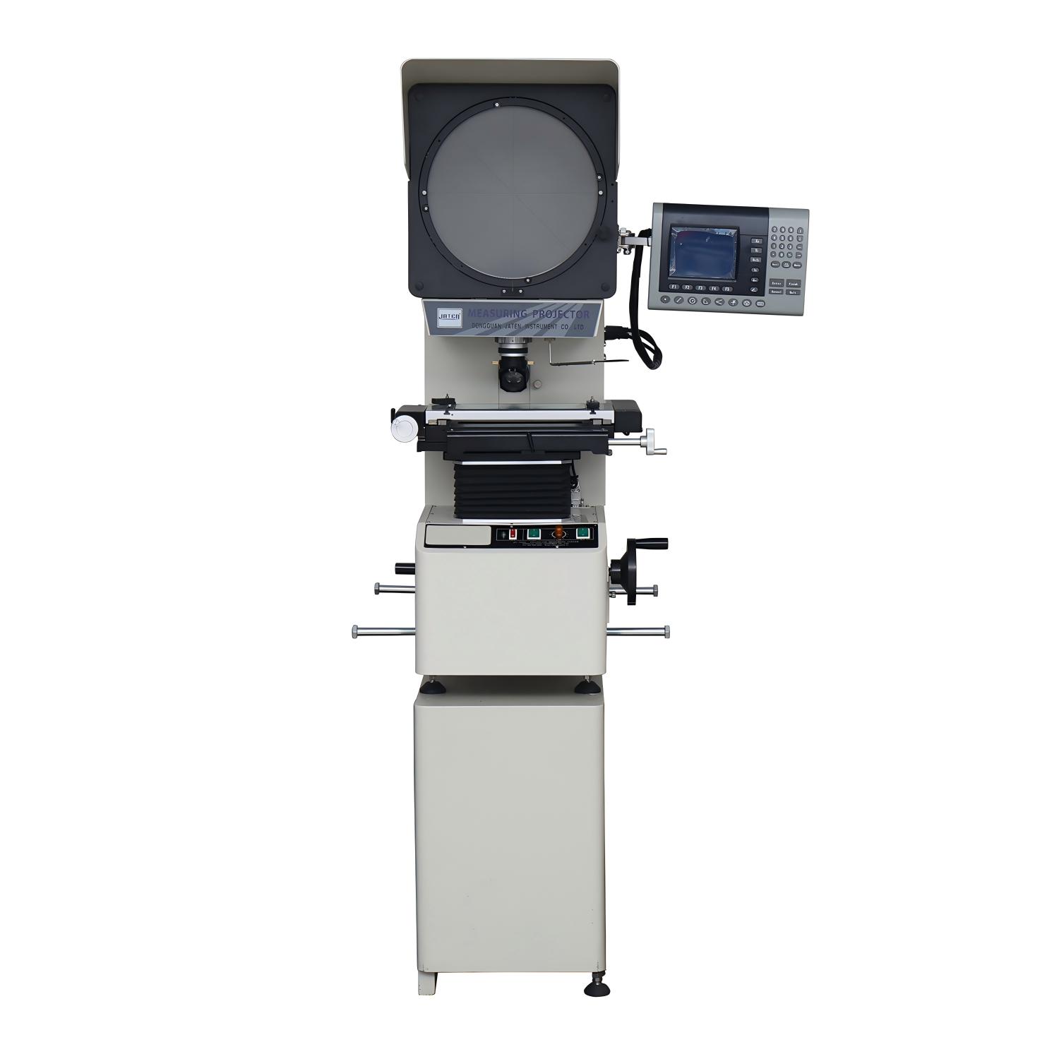
The raw casting arrives with a skin of foundry scale and a web of internal stresses frozen into its graphite-flake matrix. Before any optical component can be bolted down, the top surface is roughed flat, then the part rests for a day or two to let the metal move. A second pass with a sharp carbide insert brings the mounting face to within a few tenths of a thousandth of an inch over the full length.
Cast iron cuts with a crumbly chip and showers fine black dust, so keeping the guideways clean matters as much as the feed rate. The machinist watches for chatter near the corners where the casting is thinnest and adjusts the spindle speed by ear. Each pass removes only a whisper of material, because taking too much at once can pull the surface out of flat and leave a hump that would tilt a mirror mount.
The finished base doesn't just hold parts steady; it defines the reference plane for the entire light path. A 0.0005-inch slope across the mounting pads can send a beam off by several millimeters at the far end of the bench. That's why the final scraping or grinding is checked with a granite surface plate and a dial indicator, not just a quick pass with a straightedge.
Vacuum Coating the Mirrors for Maximum Reflectivity
Achieving peak mirror performance hinges on applying coatings in a high-vacuum chamber, where pressures drop below 10⁻⁵ torr to eliminate contaminants and gas collisions. Inside this controlled environment, a crucible vaporizes metals such as aluminum or silver, directing a uniform atomic stream onto the mirror substrate. A rotating fixture ensures even layering, while deposition monitors track thickness with sub-nanometer precision. This process yields a dense, pinhole-free film that boosts reflectivity to over 95% across visible wavelengths.
Practical tuning of coating parameters separates mediocre results from standout optics. Adjusting evaporation rate, substrate temperature, and post-deposition annealing alters grain structure and adhesion. For example, a slower rate paired with a heated substrate promotes larger crystal grains, reducing scattering losses. A protective overcoat of silicon dioxide or magnesium fluoride adds durability without sacrificing reflectance, extending the mirror's life in humid or abrasive environments.
Field experience shows that even small vacuum leaks or residual water vapor can sabotage reflectivity, creating hazy films or patchy adhesion. Regular maintenance of diffusion pumps, cold traps, and chamber seals prevents such failures. By pairing rigorous vacuum hygiene with real-time optical monitoring, technicians consistently hit 98–99% reflectivity—turning a routine coating job into a precision optical upgrade.
Hand Assembly of Lens Mounts and Fine Adjustments
Hand assembly of lens mounts starts with verifying the mount flange sits perfectly parallel to the image plane. A technician will place the bare mount on a granite surface plate and run a dial indicator around the seating face. Any tilt beyond a few microns gets corrected by selective lapping or by replacing the shim stack. The screws holding the mount to the lens barrel are tightened in a star pattern, usually with a preset torque driver, because uneven clamping force is enough to skew the whole optical axis.
Once the mount is bolted down, fine adjustments move to the back focal distance. A collimator or a test body with a ground glass screen is used to check focus at infinity. If the lens overshoots or undershoots, thin brass shims are added or removed behind the mount. Most bayonet systems tolerate no more than 0.01 mm of error here. It is common to go through three or four shim combinations before the focus confirmation stays sharp across the full frame.
Centering the mount relative to the optical axis is the last step. A laser alignment tool is projected through the lens, and the mount's radial position is adjusted with set screws until the beam lands dead center on the target. Some builders also rotate the lens on a V-block and watch the beam trace a circle; the goal is a point, not a loop. After final tightening, a drop of low-strength thread locker keeps the adjustment from drifting during normal handling.
Laser Calibration Against a Certified Master Grid
Aligning a laser system to a certified master grid begins with understanding the physical reference points that define the grid. The grid itself is a precision-etched or lithographically produced plate, often made from low-expansion glass or ceramic, with positional accuracy traceable to national standards. During calibration, the laser's beam is directed at multiple known intersections on the grid, and any deviation in beam position is measured using high-resolution position sensors. This process corrects for drift, thermal expansion, and optical path errors that accumulate over time.
One practical approach involves placing the master grid at the same working plane where the laser normally operates. The laser head is commanded to move to a sequence of grid coordinates, and a vision system or photodetector records the actual spot location. The difference between commanded and measured positions forms an error map. This map is then applied as a software correction to the laser's controller, effectively warping the coordinate system so that the laser aligns with the physical grid across its entire travel range.
Regular re-calibration against the master grid is necessary because mounting surfaces shift, lenses slightly deform under heat, and encoders lose resolution over years of service. The master grid itself remains stable, serving as an unchanging reference that exposes even sub-micron misalignments. By repeating the calibration procedure at scheduled intervals or after significant hardware changes, facilities ensure that laser cutting, engraving, or measurement systems maintain the same accuracy level as the day they were first commissioned.
Custom Stages and the Final Quality Audit
Every production line carries its own rhythm, and forcing a one-size-fits-all inspection model often leaves blind spots. That’s why we build custom stage gates around the specific failure patterns we’ve seen in your product category, not from a generic checklist. Before anything reaches the final audit, each station already knows what “done” looks like for a given batch—whether that means torque values on a subassembly, firmware version checks on embedded boards, or surface finish tolerances that only matter under certain lighting.
The final quality audit itself is less of a single event and more of a controlled argument against release. We don’t just re-run the same tests; we sample from the custom stages to see if any drift slipped through, then challenge the packaging, documentation, and even the serial number mapping against the order intent. If a unit has passed every custom gate, it should survive this last interrogation without drama—but when it doesn’t, we stop the line and trace backward until we find the exact custom stage where the logic failed.
That backward trace is where the custom part pays off. Instead of treating the final audit as a catch-all, we use it as a diagnostic mirror for the stage design itself. Each finding triggers a small revision to the custom criteria, tightening a tolerance here or adding a visual cue there, so the next batch moves through cleaner. Over time, your final audit stops being a bottleneck and becomes a quiet confirmation that the whole sequence actually understood the product.
FAQ
The process usually starts with stress-relieving the cast iron or granite base. We let the raw material rest for weeks in a temperature-stable room so internal stresses settle out before any machining begins. Skipping this step leads to slow dimensional drift later.
The projection screens are not ordinary glass. We use a fine-ground, acid-etched surface that diffuses light without creating hotspots. Each screen is inspected under a collimated light source, and if the grain size varies by more than a few microns, it gets rejected.
Air bearings remove metal-to-metal contact, so there is no stick-slip motion when an inspector moves the stage by a micron. That smoothness matters when you are trying to align a tiny thread profile with the chart overlay. The trade-off is you need a clean, dry air supply.
We use glass chrome-on-quartz reticles with patterns traceable to national standards. A 10x lens, for example, must show a 1 mm feature as exactly 10 mm on the screen. The tolerance is usually within 0.1%, and we check five points across the field, not just the center.
Each lens element is centered in its cell using a laser alignment jig before being locked in place. We also run a distortion map on every finished optical path. If the map shows barrel distortion above 0.05%, the lens stack gets rebuilt rather than compensated in software.
A finished comparator runs a repeated measurement cycle for 48 hours with the lamp cycling on and off. We watch for stage drift, screen warping, and light intensity changes. Any unit that moves more than 2 microns during the test goes back to the assembly bench.
Yes, most factories offer custom workholding and chart overlays. We often receive a CAD file of the part, then laser-etch a matching overlay on glass. The projector itself might get a longer stage travel or a special lens magnification like 50x or 100x if the feature is very small.
Halogen has a broad, continuous spectrum that matches older optical coatings well. But factories are shifting to warm-white LEDs with a phosphor mix that mimics halogen. The key is maintaining a stable color temperature so the screen image does not shift hue during long inspections.
Conclusion
Inside a profile projector factory, the process begins well before any optical comparator takes shape. In the furnace room, raw glass batches are melted and slowly cooled into blanks, then ground and polished into precision lenses whose surface accuracy is measured in millionths of an inch. Meanwhile, the heavy cast iron base that anchors the entire light path is machined on CNC mills to hold every optical element in rigid alignment, because even a few microns of flex can throw off a measurement. After the base is finished, the mirrors receive a vacuum-deposited reflective coating, applied layer by layer in a sealed chamber to maximize light throughput and minimize scatter across the projection screen.
From there, the work moves to a bench where lens mounts are hand-fitted with fine adjustment screws and springs, each one tuned by feel rather than torque alone. Once the optics and mechanics are mated, every instrument goes through laser calibration against a certified master grid, comparing projected line positions to a traceable standard and compensating for any residual distortion. Custom stages are then installed and aligned to the customer’s specific travel and bearing requirements. Finally, a full quality audit checks not just the calibration data but also the feel of the stage movement, the clarity of the projected image, and the repeatability of the focusing mechanism. Only when every detail passes does the comparator leave the floor, ready to measure parts that other inspection tools cannot see clearly.
Contact Us
Contact Person: Volien
Email: [email protected]
Tel/WhatsApp: +86 18029161762
Website: https://www.jatentech.com/